|
According to the Faraday's Induction Law, the induced eddy current flows in an electrical metal conductor,
if the conductor is located in a time changeable magnet field. The magnet field is generated here by an
aternating current flowing in a wire coil. The eddy current generates a opposite magnet field, which
superimposes with the exciting magnet field. As consequence, the impedance Z
of the sensor coil changes.
The impedance change depends on the distance a between the measuring target (metal plate)
and sensor, and on material of the target. For a defined measuring target the change
of coil impedance is a function of the distance a. Therefore, the distance can be derived by
measuring impedance change. Using an Impedance-Voltage Converter (Fig. 2), the impedance change can
be converted into a voltage change for further signal processing.
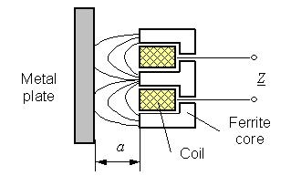 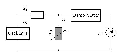
Fig. 1 Eddy current position sensor
Fig.2 Impedance-Voltage converter
Eddy current sensors work most efficently at high-oscillation frequencies nearby their resonance frequencies.
The resonance frequency of an eddy current sensor depends on the sensor coil. The serial impedance Zs
must be high enough in order to obtain a high sensitivity. After demodulation of the output voltage u one obtains the
output voltage U as function of the distance a. Fig. 3 shows the output signal at different frequencies.
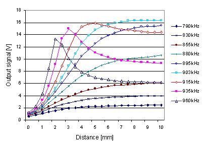
Fig. 3 Response voltage of an eddy current position sensor nearby the resonance frequency 903kHz
using a aluminium plate as target
Eddy current sensor performance is related to the change in sensor coil impedance over the calibrated range of target motion.
High impednce change per unit of displacement is near the target, and low change farthest from the target. At the resonance frequency
(903kHz for a sensor coil with winding number 200) the output voltage changes from 1.2V/mm to 3.96V/mm in a measuring range of 5mm.
For a smaller measuring range of 2mm the output voltage is from 3V/mm to 5.6V/mm at the frequency 915kHz. Therefore a high
resolution of 0.5nm for small distance measurment is realizable using a exciting frequency over the resonance frequency.
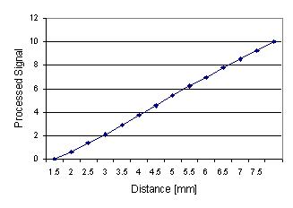
Fig. 4 Linearization of the output signal of an eddy current sensor for increasing the measuring range
(The optimale excitation frequency is 810kHz for the example sensor)
In order to increase the measuring range of an eddy current sensor, the linearity of the output signal must be improved by signal processing.
The output signal at frequencies lower than the resonance frequency approximates an exponential function. In this case one can use analog signal
processing to linearize the output voltage. Fig. 4 shows an example of output signal linearization at an optimale frequency of 810kHz. The linear range of
the processed signal is larger than that of the original signal. A linearity less than 0.1% is realizable after the sensor optimization.
Special sensor electronics, signal processing and self-calibration are developed for compensation
of temperature and material influences. Thus, the developed distance eddy current sensors are independent
on measuring objects and can be used under normal measuring conditions for precise position, distance and vibration measurements.
Force and stress measurement using eddy current sensors
|