|
1. Force and Stress Measurement
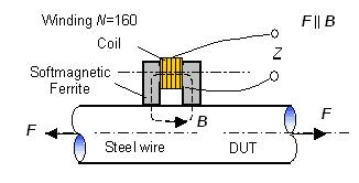 An eddy current sensor consists of a ferrite U-core and a coil. The force and stress measurement
is based on the permeability change of the device under test (DUT) caused by an applying force on
it. As result the impedance of the sensor coil changes with the applying force. The impedance
change can be converted into a voltage change by using a measuring bridge. The force and stress
applied on the DUT can be derived by the voltage measurement.
An eddy current sensor consists of a ferrite U-core and a coil. The force and stress measurement
is based on the permeability change of the device under test (DUT) caused by an applying force on
it. As result the impedance of the sensor coil changes with the applying force. The impedance
change can be converted into a voltage change by using a measuring bridge. The force and stress
applied on the DUT can be derived by the voltage measurement.
The sensitivity, linearity and hysteresis of an eddy current force and stress sensor depend
strongly on measuring conditions, i.e., exciting current and testing frequency. The testing
conditions must be optimized to obtain a high sensor sensitivity, a good linearity and a low
hysteresis. The testing frequency is normally selected between 100 Hz and 10 kHz. In this case
the optimal exciting current changes from 25mA to 50mA.
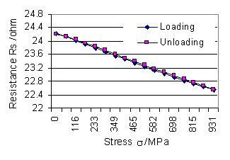
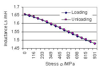
Fig.2 Relation between impedance and stress of
loading and unloading
The relation between the measuring impedance and the applying stress is nearly linear under
the optimized measuring conditions. The mean correlation coefficient is better than -0.996.
The hysteresis of the loading and unloading curves is less than 3%.
Fig.3 shows the sensitivity and hysteresis of both measuring quantities Rs and Ls
as a function of the exciting frequency. Using these graphics the optimal frequency can be easily
derived.
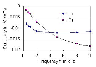
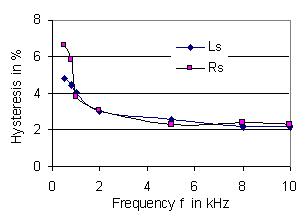
Fig.3 Sensitivity and hysteresis as function of the exciting
frequency
The developed eddy current sensors can be applied to the force and stress measurement of tensioned
steel elements, the monitoring of pre-stressed bridge cables and concrete structures etc.
2. Residual Stress Measurement
 The developed eddy current sensors can also be used for the measurement of residual stress in steel
elements. To optimize the testing conditions of an eddy current sensor for the measurement of residual
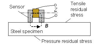
stress, three reference specimens (80x15x9 mm3) are used as device
under test. The sensor setup is shown in the left figure. The specimens have a tensile stress profile
on one side and a pressure stress profile on the opposite side.
Fig.5 shows parameter changes of coil impedance measured between tensile and pressure residual stress
as function of exciting current and frequency. The relative parameter changes reach their maximum when
the exciting current I=20 mA.
The resistance change is less than the inductance change in the lower frequency range, and vice versa
in the higher frequency range. The optimal frequency range for the two parameters are between 500 Hz
and 20 kHz.
The developed eddy current sensors can also be used for the measurement of residual stress in steel
elements. To optimize the testing conditions of an eddy current sensor for the measurement of residual
stress, three reference specimens (80x15x9 mm3) are used as device
under test. The sensor setup is shown in the left figure. The specimens have a tensile stress profile
on one side and a pressure stress profile on the opposite side.
Fig.5 shows parameter changes of coil impedance measured between tensile and pressure residual stress
as function of exciting current and frequency. The relative parameter changes reach their maximum when
the exciting current I=20 mA.
The resistance change is less than the inductance change in the lower frequency range, and vice versa
in the higher frequency range. The optimal frequency range for the two parameters are between 500 Hz
and 20 kHz.
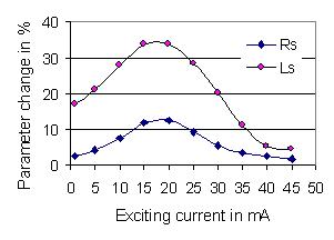
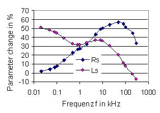
Fig.5 Parameter changes as function of the exciting frequency
and current
The developed sensors react sensitively to the change of residual stress in the specimens. In
the frequency range from 500 Hz to 20 kHz the sensitivity of the resistance Rs and inductance Ls are
variable between 0.026 % MPa-1 to 0.049 % MPa-1
. This is the double of the sensitivity of force and stress measurement using the same sensor.
The developed eddy current sensor array can be used for the measurement of residual stress of steel
elements in the automobil industry and maschine building.
These measuring methods are developed at the Department of Electrical Engineering of the University of Kassel.
Displacement and position measurement using eddy current sensors
|