|
The characterization of length, distance and position sensors/transducers is based on the measurements
of the linearity and deviation of their output signals and displays etc. Laser interferometers are
usually applied to the precise measurements of length sensors and transducers. This is an expensive
solution for engineering applications. A cost favourable measuring and testing system is developed
by applying a self-correction measuring method. The following figure shows a scheme of self-corrected
measuring and testing system.
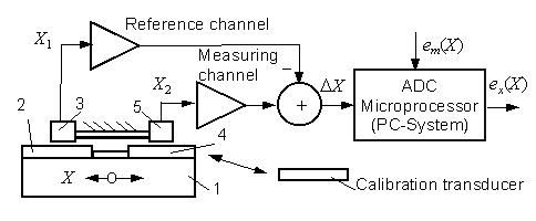
1: Moveable table
2: Reference transducer
3: Reference detector
4: Measuring transducer
5: Measuring detector
This system consists of a reference channel and a measuring channel. A difference measurement is
realized by using the both channels so that the influences from temperature change can be compensated
if the material of reference transducer is the same of the measuring transducer.
In order to compensate the measuring deviation, the measuring and testing system is calibrated
in advance with the use of a calibratoion transducer. The calibration data em
(X) are stored as correction matrix in the PC-System.
The measuring result ex(X) can automatically be corrected
according to the correction matrix.
Therefore, the accuracy of the self-corrected measuring and testing system depends on the tolerance
of calibration transducer. If the calibration transducer is calibrated with a laser interferometer
in advance, its deviation can be included in the correction matrix. Thus, the deviation of the calibration
transducer can also compensated by the correction algorithm. The accuracy of this measuring and
testing system is comparable with that of the laser interferometer used for calibrating the calibration
transducer. This measurimg and testing system can be operated under normal surrounding conditions.
|