|
Impedance measuriement is one of the most important parts of the measurements of electrical quantities,
because the impedance is a fundamental quantity of material characterization, different electrical and
magnetic elements, components and sensors etc. Different impedance measurement techniques, such as oscillators,
frequency domain techniques, and digital AC bridges, etc., have been developed in the last decades to
satisfy the increasing requirements. For precise measurements, however, these measuring methods need
precise measuring hardware.
In order to improve the measuring accuracy with lower product cost one uses the modern signal
processing techniques, such as Discrete Fourier Transform (DFT), and error correction to the impedance
measurement. The signal processing forms the fundamentals for the error correction and contributes
also to the improvement of the repeatability of the measuring systems. The used software has the
principle advantage of a long-term stability.
Most error correction methods, however, are based on the calibration in advance. In the last decades
some well-known calibration methods, such as OPEN, SHORT and LOAD, have been developed specially for
impedance measurements. In these methods, for example, OPEN and SHORT, zero-impedance is used as reference
value for the calibration. This, however, cannot satisfy the measuring accuracy in many cases because
only offset error is determined by the Zero-Impedance-Calibration. The measuring errors of impedance
measurement are a complex function of the measurand so that reference impedance valued in the whole
measuring range is needed for the calibration of the measuring system. This requirement leads to the
development of a Self-Calibration Measuring Method for precise impedance measurement.
In a self-calibrated impedance measuring system, precise reference elements (resistances and capacitors)
are integrated for the self-calibration. The measuring errors of fundamental system can be compensated by
the signal processing using the self-calibration measuring data. The measuring accuracy of the resulted
measuring system depends only on the tolerance of the reference elements.
As example two simple self-calibrated measuring systems are given in the following.
Example 1
Fig.1 shows a self-calibrated measuring system of capacitance measurement. Two reference capacitors
Cr1 and Cr2 are used for the self-calibration.
During the self-calibration the references are connected to the measuring circuit.
The transfer functions Gr1 and Gr2 are determined
by a Fourier-Series with the use of sampled input and output signals ui(t) and
uo(t). For the measurement, the measuring capacitor Cx
is connected to the measuring circuit by the multiplexer (MUX). In this case one obtains the transfer
function Gx in the same way.
The measuring result can be determined by a linear interpolation:
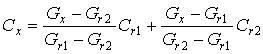
The total deviation of measuring system can be compensated by the linear interpolation. The measuring
accuracy of the capacitance is dependent only on the tolerance of the reference capacitors.
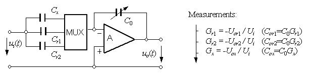
Fig.1 Self-calibrated measuring system for capacitance measurement
Example 2
Dielectric and piezoelectrical materials are driven in many cases e.g. in actuators and sensors
under a high electrical field intensity. The field intensity is generated by DC and AC components.
As example a measuring circuit shown in Fig. 2 is given for the impedance measurement of dielectric
and piezoelectrical materials under high field intensity. To generate a high exciting voltage,
an amplifier with a gain of A is used in the measuring circuit.
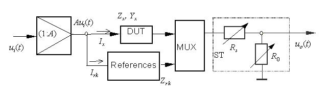
Fig. 2 Self-calibrated impedance measruing circuit under high field intensity
The application of a measuring circuit without self-calibraation is connected with two problems.
Firstly, the magnitude and phase deviations of the transfer function of the amplifier influence the
measuring accuracy of the impedance measurement. These errors are changed with the test frequency
and the height of voltage so that it is difficult to correct them by means of the software.
Secondly, a high electrical field intensity can exceed the threshold voltage at the input channel
of the voltage measring instrument if the device under test (DUT) is defect. In this case the measuring
channel can be broken by the exceeding voltage. Therefore, the measuring system must be safeguarded
by a necessary measure against the overdriving voltage.
These two problems can be solved together by applying a self-calibration to this measuring system.
Calibration resistors are used as references in this measuring circuit. The both resistors
Rs and R0 forms a voltage adapter. The offset resistor Rs
serves as system safty element. The overdriving voltage can be reduced by the voltage adapter.
With the calibration resistors the measuring system can be self-calibrated under the required measuring
conditions before the measurement and safeguarded in the overdriving case mentioned above. By means
of this technique the systematic error of the measuring system is fully corrected and the system safety
is automatically guaranteed.
|